

To put my RaspberryPi (which was only laying around) to good use i decided to do a quick hack. Combined with a small 2.4 inch display, it shows the current status of the button from reddit.

A small python script connects to the reddit websocket server and displays the status of the timer, the number of participants and the current record since the script is running.
To run the script:
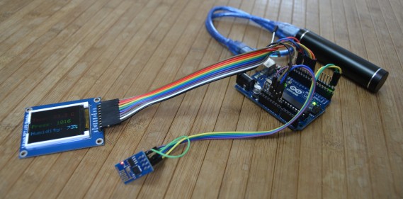
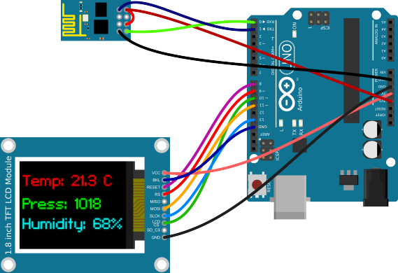
This is my first attempt to receive data with an Arduino and the ESP8266 WiFi-Module. This program is based on the example by Seedstudio, and displays weather data on a small TFT display.
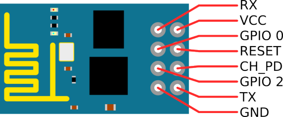
I bought this module at Electrodragon. This Version has two LEDs, one for Power and another one which is connected to the TX-Pin. It runs at 3.3 Volt and the serial port is set to a data rate of 115200 baud. The CH_PD-Pin has to be high. After a reset, the module sends the following data:
[code]
AT+RST
OK
ets Jan 8 2013,rst cause:4, boot mode:(3,6)
wdt reset
load 0x40100000, len 24236, room 16
tail 12
chksum 0xb7
ho 0 tail 12 room 4
load 0x3ffe8000, len 3008, room 12
tail 4
chksum 0x2c
load 0x3ffe8bc0, len 4816, room 4
tail 12
chksum 0x46
csum 0x46
ready
[/code]
The wiring is quite simple. The wifi-module needs just two wires for power and two for the serial interface. As a display i used a 1.8″ (45.72 mm) TFT-display that is connected via SPI.
| Arduino | ESP8266 Module | Display Module |
|---|---|---|
| 3.3V | VCC & CH_PD | – |
| 5V | – | VCC |
| GND | GND | GND & BKL |
| 0 (RX) | TX | – |
| 1 (TX) | RX | – |
| 8 | – | RESET |
| 9 | – | RS |
| 10 | – | LCD CS |
| 11 | – | MOSI |
| 13 | – | SLCK |
I changed the source code from Seedstudio a little bit, because at 115200 baud the 64 Byte uart-buffer from the Arduino fills up very fast. But overall the program is really simple.
[code language=”java”]
#include <SoftwareSerial.h>
#include <JsonParser.h>
#define cs 10 // Pins for the display
#define dc 9
#define rst 8
#include <Adafruit_GFX.h> // Core graphics library
#include <Adafruit_ST7735.h> // Hardware-specific library
#include <SPI.h>
Adafruit_ST7735 tft = Adafruit_ST7735(cs, dc, rst);
using namespace ArduinoJson::Parser;
#define SSID "<ssid>" // insert your SSID
#define PASS "<password>" // insert your password
#define LOCATIONID "2925533" // location id
#define DST_IP "188.226.224.148" //api.openweathermap.org
SoftwareSerial dbgSerial(2, 3); // RX, TX for debugging
JsonParser<32> parser;
void setup()
{
Serial.begin(115200);
Serial.setTimeout(5000);
dbgSerial.begin(9600); // for debuging
dbgSerial.println("Init");
tft.initR(INITR_BLACKTAB);
tft.setRotation(1);
tft.fillScreen(ST7735_BLACK);
tft.setCursor(2, 2);
tft.setTextColor(ST7735_WHITE);
Serial.println("AT+RST"); // restet and test if module is redy
delay(1000);
if(Serial.find("ready")) {
dbgSerial.println("WiFi – Module is ready");
tft.println("WiFi – Module is ready");
}else{
dbgSerial.println("Module dosn’t respond.");
tft.println("Module dosn’t respond.");
tft.println("Please reset.");
while(1);
}
delay(1000);
// try to connect to wifi
boolean connected=false;
for(int i=0;i<5;i++){
if(connectWiFi()){
connected = true;
tft.println("Connected to WiFi…");
break;
}
}
if (!connected){
tft.println("Coudn’t connect to WiFi.");
while(1);
}
delay(5000);
Serial.println("AT+CIPMUX=0"); // set to single connection mode
}
void loop()
{
String cmd = "AT+CIPSTART=\"TCP\",\"";
cmd += DST_IP;
cmd += "\",80";
Serial.println(cmd);
dbgSerial.println(cmd);
if(Serial.find("Error")) return;
cmd = "GET /data/2.5/weather?id=";
cmd += LOCATIONID;
cmd += " HTTP/1.0\r\nHost: api.openweathermap.org\r\n\r\n";
Serial.print("AT+CIPSEND=");
Serial.println(cmd.length());
if(Serial.find(">")){
dbgSerial.print(">");
}else{
Serial.println("AT+CIPCLOSE");
dbgSerial.println("connection timeout");
tft.fillScreen(ST7735_BLACK);
tft.setCursor(2, 2);
tft.setTextColor(ST7735_WHITE);
tft.println("connection timeout");
delay(1000);
return;
}
Serial.print(cmd);
unsigned int i = 0; //timeout counter
int n = 1; // char counter
char json[100]="{";
while (!Serial.find("\"main\":{")){} // find the part we are interested in.
while (i<60000) {
if(Serial.available()) {
char c = Serial.read();
json[n]=c;
if(c==’}’) break;
n++;
i=0;
}
i++;
}
dbgSerial.println(json);
JsonObject root = parser.parse(json);
double temp = root["temp"];
double pressure = root["pressure"];
double humidity = root["humidity"];
temp -= 273.15; // from kelvin to degree celsius
tft.fillScreen(ST7735_BLACK);
tft.setCursor(2, 25);
tft.setTextColor(ST7735_BLUE);
tft.setTextSize(2);
tft.print("Temp: ");
tft.print((int)temp);
tft.print(".");
tft.print((int)((temp-(int)temp)*10));
tft.println(" C");
tft.setCursor(2, 55);
tft.setTextColor(ST7735_GREEN);
tft.setTextSize(2);
tft.print("Press: ");
tft.print((int)pressure);
tft.setCursor(2, 85);
tft.setTextColor(ST7735_YELLOW);
tft.setTextSize(2);
tft.print("Humidity: ");
tft.print((int)humidity);
tft.println("%");
dbgSerial.println(temp);
dbgSerial.println(pressure);
dbgSerial.println(humidity);
dbgSerial.println("====");
delay(600000);
}
boolean connectWiFi()
{
Serial.println("AT+CWMODE=1");
String cmd="AT+CWJAP=\"";
cmd+=SSID;
cmd+="\",\"";
cmd+=PASS;
cmd+="\"";
dbgSerial.println(cmd);
Serial.println(cmd);
delay(2000);
if(Serial.find("OK")){
dbgSerial.println("OK, Connected to WiFi.");
return true;
}else{
dbgSerial.println("Can not connect to the WiFi.");
return false;
}
}
[/code]
The program is quite simple and could be extended with more features like a weather forecast. If you have any comments about the source code leave it down below. I hope i don’t have to many spelling mistakes in my first English post 🙂
Update: There was a bug in the code, which was found by Jody Roth. This is now fixed.
Dies ist mein erster Versuch mit einem ESP8266 WiFi-Modul und einem Arduino Daten zu laden. Das Programm auf dem Arduino basiert auf dem Beispiel von Seedstudio, holt aktuelle Wetterdaten von openweathermap.org und zeigt diese auf einem kleinen Display an.
Das Modul habe ich bei Electrodragon gekauft. Diese Version hat zwei LEDs, eine rote Power-LED und eine TX-LED. Das Modul läuft mit 3.3 Volt und die serielle Schnittstelle ist auf 115200 baud eingestellt. Der CH_PD-Pin muss auf high liegen. Nach einem Reset gibt das Modul folgendes über die serielle Schnittstelle aus:
[code]
AT+RST
OK
ets Jan 8 2013,rst cause:4, boot mode:(3,6)
wdt reset
load 0x40100000, len 24236, room 16
tail 12
chksum 0xb7
ho 0 tail 12 room 4
load 0x3ffe8000, len 3008, room 12
tail 4
chksum 0x2c
load 0x3ffe8bc0, len 4816, room 4
tail 12
chksum 0x46
csum 0x46
ready
[/code]
Die Verkabelung ist ziemlich einfach. Das Modul braucht nur jeweils zwei Leitungen für die Stromversorgung und die serielle Kommunikation. Als Display habe ich ein 1.8 Zoll (45.72 mm) TFT-Display genommen das via SPI-Schnittstelle angesteuert wird.
| Arduino | ESP8266 Module | Display Module |
|---|---|---|
| 3.3V | VCC & CH_PD | – |
| 5V | – | VCC |
| GND | GND | GND & BKL |
| 0 (RX) | TX | – |
| 1 (TX) | RX | – |
| 8 | – | RESET |
| 9 | – | RS |
| 10 | – | LCD CS |
| 11 | – | MOSI |
| 13 | – | SLCK |
Den Quellcode von Seedstudio habe ich etwas abgeändert. Da bei 115200 baud der 64Byte UART-Buffer des Arduino schnell voll ist, wird der Buffer so schnell wie möglich geleert. Ansonsten ist das Programm ziemlich einfach gestrickt.
[code language=”java”]
#include <SoftwareSerial.h>
#include <JsonParser.h>
#define cs 10 // Pins for the display
#define dc 9
#define rst 8
#include <Adafruit_GFX.h> // Core graphics library
#include <Adafruit_ST7735.h> // Hardware-specific library
#include <SPI.h>
Adafruit_ST7735 tft = Adafruit_ST7735(cs, dc, rst);
using namespace ArduinoJson::Parser;
#define SSID "<ssid>" // insert your SSID
#define PASS "<password>" // insert your password
#define LOCATIONID "2925533" // location id
#define DST_IP "188.226.224.148" //api.openweathermap.org
SoftwareSerial dbgSerial(2, 3); // RX, TX for debugging
JsonParser<32> parser;
void setup()
{
Serial.begin(115200);
Serial.setTimeout(5000);
dbgSerial.begin(9600); // for debuging
dbgSerial.println("Init");
tft.initR(INITR_BLACKTAB);
tft.setRotation(1);
tft.fillScreen(ST7735_BLACK);
tft.setCursor(2, 2);
tft.setTextColor(ST7735_WHITE);
Serial.println("AT+RST"); // restet and test if module is redy
delay(1000);
if(Serial.find("ready")) {
dbgSerial.println("WiFi – Module is ready");
tft.println("WiFi – Module is ready");
}else{
dbgSerial.println("Module dosn’t respond.");
tft.println("Module dosn’t respond.");
tft.println("Please reset.");
while(1);
}
delay(1000);
// try to connect to wifi
boolean connected=false;
for(int i=0;i<5;i++){
if(connectWiFi()){
connected = true;
tft.println("Connected to WiFi…");
break;
}
}
if (!connected){
tft.println("Coudn’t connect to WiFi.");
while(1);
}
delay(5000);
Serial.println("AT+CIPMUX=0"); // set to single connection mode
}
void loop()
{
String cmd = "AT+CIPSTART=\"TCP\",\"";
cmd += DST_IP;
cmd += "\",80";
Serial.println(cmd);
dbgSerial.println(cmd);
if(Serial.find("Error")) return;
cmd = "GET /data/2.5/weather?id=";
cmd += LOCATIONID;
cmd += " HTTP/1.0\r\nHost: api.openweathermap.org\r\n\r\n";
Serial.print("AT+CIPSEND=");
Serial.println(cmd.length());
if(Serial.find(">")){
dbgSerial.print(">");
}else{
Serial.println("AT+CIPCLOSE");
dbgSerial.println("connection timeout");
tft.fillScreen(ST7735_BLACK);
tft.setCursor(2, 2);
tft.setTextColor(ST7735_WHITE);
tft.println("connection timeout");
delay(1000);
return;
}
Serial.print(cmd);
unsigned int i = 0; //timeout counter
int n = 1; // char counter
char json[100]="{";
while (!Serial.find("\"main\":{")){} // find the part we are interested in.
while (i<60000) {
if(Serial.available()) {
char c = Serial.read();
json[n]=c;
if(c==’}’) break;
n++;
i=0;
}
i++;
}
dbgSerial.println(json);
JsonObject root = parser.parse(json);
double temp = root["temp"];
double pressure = root["pressure"];
double humidity = root["humidity"];
temp -= 273.15; // from kelvin to degree celsius
tft.fillScreen(ST7735_BLACK);
tft.setCursor(2, 25);
tft.setTextColor(ST7735_BLUE);
tft.setTextSize(2);
tft.print("Temp: ");
tft.print((int)temp);
tft.print(".");
tft.print((int)((temp-(int)temp)*10));
tft.println(" C");
tft.setCursor(2, 55);
tft.setTextColor(ST7735_GREEN);
tft.setTextSize(2);
tft.print("Press: ");
tft.print((int)pressure);
tft.setCursor(2, 85);
tft.setTextColor(ST7735_YELLOW);
tft.setTextSize(2);
tft.print("Humidity: ");
tft.print((int)humidity);
tft.println("%");
dbgSerial.println(temp);
dbgSerial.println(pressure);
dbgSerial.println(humidity);
dbgSerial.println("====");
delay(600000);
}
boolean connectWiFi()
{
Serial.println("AT+CWMODE=1");
String cmd="AT+CWJAP=\"";
cmd+=SSID;
cmd+="\",\"";
cmd+=PASS;
cmd+="\"";
dbgSerial.println(cmd);
Serial.println(cmd);
delay(2000);
if(Serial.find("OK")){
dbgSerial.println("OK, Connected to WiFi.");
return true;
}else{
dbgSerial.println("Can not connect to the WiFi.");
return false;
}
}
[/code]
Das Programm ist sehr einfach gehalten, und eigentlich könnte man noch mehr Daten anzeigen. Wenn ihr Verbesserungsvorschläge habt, schreibt sie einfach in die Kommentare.
Hier noch zwei Links mit weiteren Informationen:
Update: Es hat sich ein kleiner Programmierfehler eingeschlichen, aber Jody Roth hat ihn entdeckt. Der Fehler ist jetzt behoben.
Zur Erstellung der Fallblatanzeigen-Sprites habe ich zwei GIMP Plugins geschrieben. Hier ist eine Anleitung einer ersten Alpha-Version 🙂 Wir beginnen mit dem Hintergrund für unsere Anzeige.
![]()
Nun benutzen wir das erste Script. Das “Create Static Sprite” Script erstellt aus dem ersten einzelnen Hintergrundbild ein statisches Sprite mit den Ziffern Null bis Neun. Dabei kann die Schriftart, die Farbe und ein vertikaler Offset eingestellt werden. Wenn das Sprite für einen Zähler erstellt werden soll der runter zählt, so kann die Reihenfolge der Ziffern von “0123456789” zu “9876543210” geändert werden.
![]()
Das Script erzeugt nun ein neues Bild welches zehn mal so Breit ist wie unsere Vorlage. Dieses Bild kann vor dem nächsten Schritt noch bearbeitet, und muss zu eine einzelne Ebene vereint werden.
![]()
Jetzt erzeugen wir mit dem zweiten Script (Create Animated Sprite) das eigentliche Sprite. Dabei kann noch ein 3D-Effekt erzeugt werden.
![]()
Auch dieses Script erstellt ein neues Bild.
![]()
… und wir sind fertig. Die Scripte sind noch sehr simpel, und es fehlen noch zahlreiche Funktionen, so kann zum Beispiel noch nicht die Anzahl der Animationsschritte eingestellt werden.
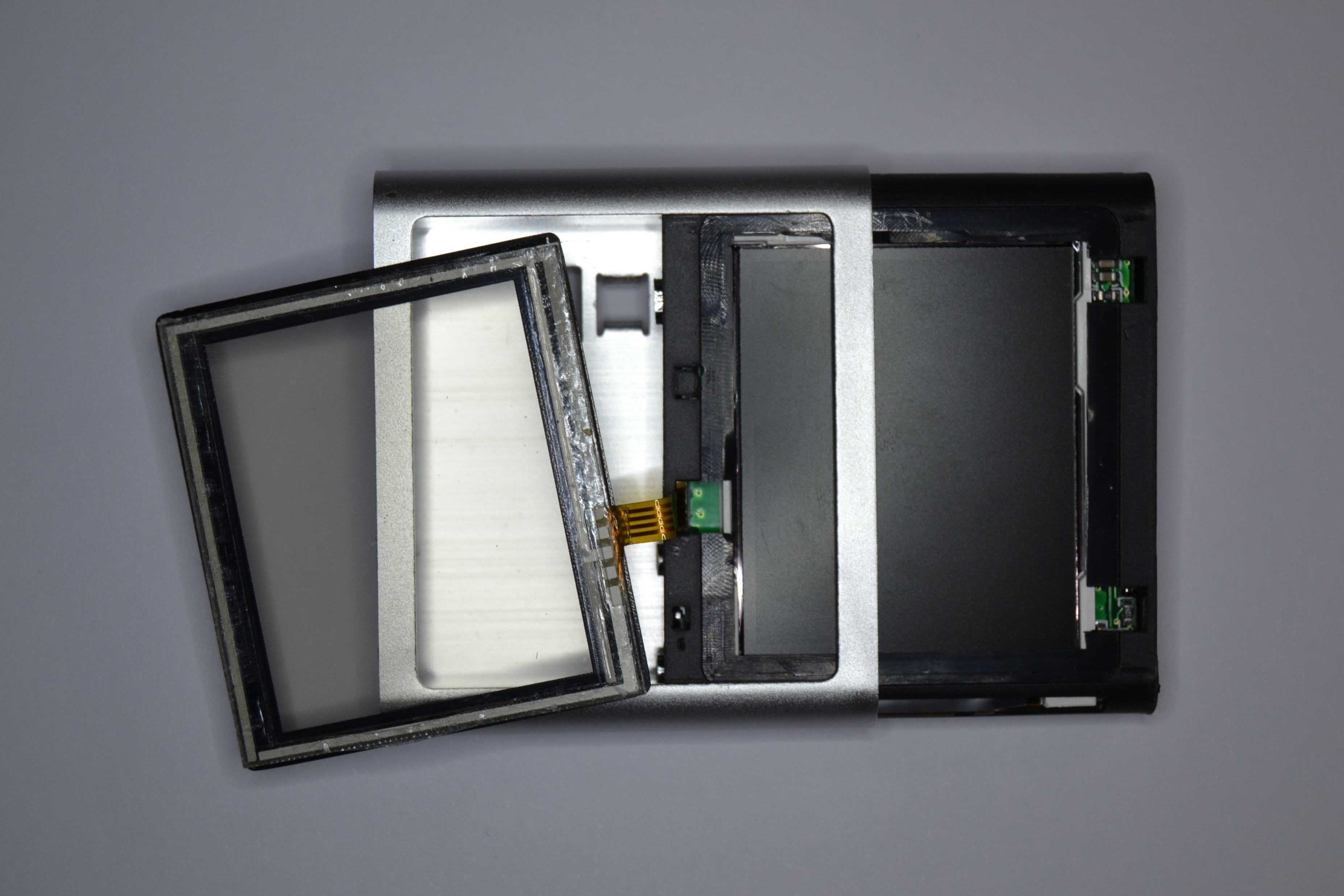
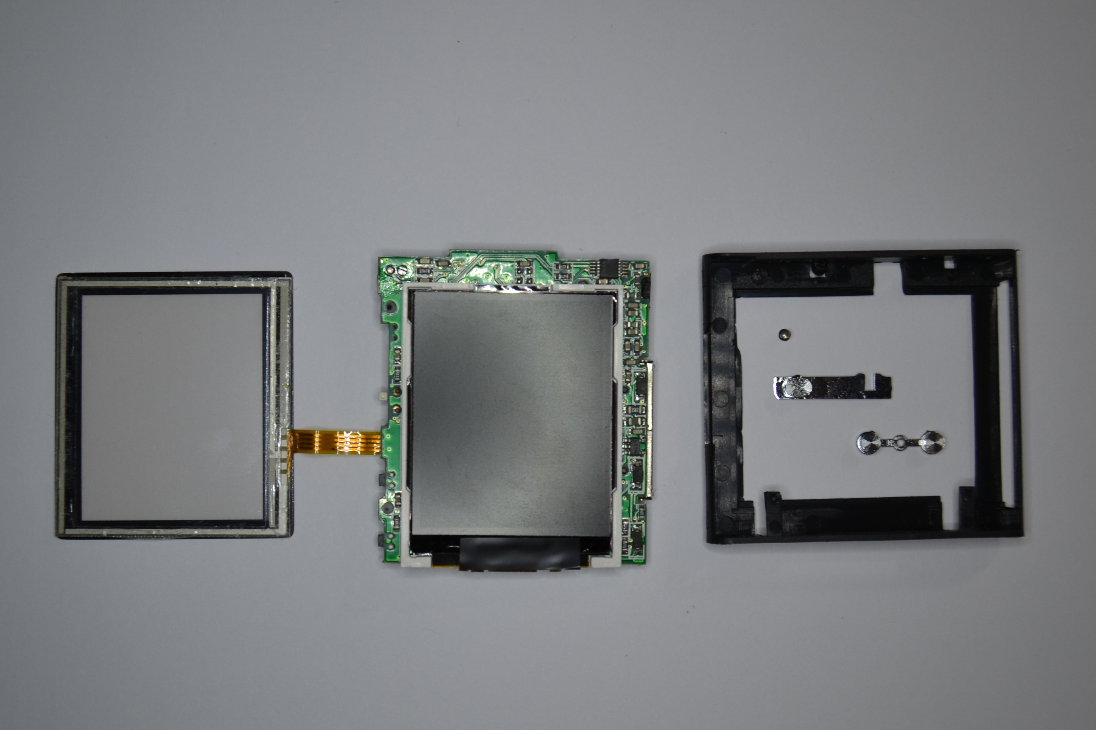
Hier einige Bilder von einem nachgemachten iPod Nano (sechste Generation).


Und noch ein kleines Projekt: Ein Board mit einer Menge Sensoren, und vielleicht passt noch ein kleines Display drauf.

Arbeite gerade an einem kleinen Projekt um mehr über TCP/IP und Mikrocontroller zu lernen. Dabei handelt es sich um eine art Arduino, nur mit Ethernet-Interface.